I originally figured out the basics of how I was going to get a signal from the motor to my in-dash digital tachometer back in October. That post is
here. I promised a "final chapter" so here it is.
I have now implemented that plan and have a working tach. I first decided to make life easy and pulled 9 batteries out of the front of the car. This gave me good access to the front of the motor.

The pieces I used to generate the tach signal were all removed from a 70's era Mopar distributor that I had in my stash of Muscle Car parts. This was the easiest and cheapest solution to the problem, since a distributor similar to this one was successfully generating the tach signal while the internal combustion engine was in the car. Figuring out how it did that was actually pretty simple.

I just replicated the sensor configuration from inside the distributor onto the front motor shaft. Proper alignment was pretty critical here so I am glad I took the time and effort to remove some batteries. One modification I had to make was to grind off four of the teeth from the sensor gear.

This was necessary because the gear originally generated 8 pulses per revolution of the distributor. An internal combustion engine has two revolutions per one revolution of the distributor. Therefore, four pulses equates to one revolution of the engine (or electric motor). The gear also needed to be bored out slightly to fit on the motor shaft.

Once the sensor unit was satisfactorily mounted, I connected it to the original ECU (electronic control unit). This unit was necessary to properly process the pulses generated by the sensor into something able to be read by the tachometer.

Of course I wanted to test it before lifting 600 pounds of batteries back into the car. I disconnected the motor from the controller and hooked up a 12 volt car battery to it - the same way I originally tested the motor. I connected a spare tachometer to my accessory 12v battery.
The test was a success. All I have to do now is run the sensor wire to the in-dash tach.


 Well it didn't actually break. It just separated from the Lovejoy coupling. I was quick to blame my amateur welding skills for this failure. However, I have discovered that the failure is much more than that.

 First, I removed the old fuel and oil pressure gauges. In addition, I relabeled the water temperature guage to read "CNTRLR". I ran a sensor wire to the controller and was hoping to use the old water temperature sender to pick up the controller temperature. (So far, it is reading way too high so I will need to play with the sensor a bit more.)
 Before I knew it, I had run quite a few new wires. I finally hooked everything back up to the dash and reinstalled it. I then tested everything including the tach. Finally, I tucked all of the loose wires under the hood and test drove the car to make sure everything still works as it should. Now I can work on completing the necessary control circuits.
 The pieces I used to generate the tach signal were all removed from a 70's era Mopar distributor that I had in my stash of Muscle Car parts. This was the easiest and cheapest solution to the problem, since a distributor similar to this one was successfully generating the tach signal while the internal combustion engine was in the car. Figuring out how it did that was actually pretty simple.
 I just replicated the sensor configuration from inside the distributor onto the front motor shaft. Proper alignment was pretty critical here so I am glad I took the time and effort to remove some batteries. One modification I had to make was to grind off four of the teeth from the sensor gear.
 This was necessary because the gear originally generated 8 pulses per revolution of the distributor. An internal combustion engine has two revolutions per one revolution of the distributor. Therefore, four pulses equates to one revolution of the engine (or electric motor). The gear also needed to be bored out slightly to fit on the motor shaft.
 Once the sensor unit was satisfactorily mounted, I connected it to the original ECU (electronic control unit). This unit was necessary to properly process the pulses generated by the sensor into something able to be read by the tachometer.
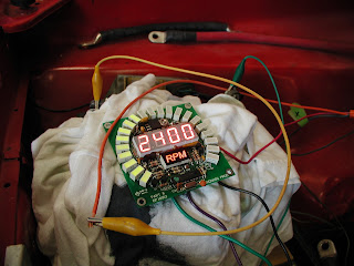
 Of course I wanted to test it before lifting 600 pounds of batteries back into the car. I disconnected the motor from the controller and hooked up a 12 volt car battery to it - the same way I originally tested the motor. I connected a spare tachometer to my accessory 12v battery.
 The test was a success. All I have to do now is run the sensor wire to the in-dash tach.

 Next, I took the old gas filler tube, cut off the end where the gas cap mounts, and welded on a couple of small tabs to mount the charger plug. Now the plug is hidden nicely behind the gas cap.


 After it broke (for no apparent reason) I did a little checking in the on-line forums and discovered that it is pretty common for these to break or lock up - even by just putting power to them in a way they "don't like". Great, more stuff learned the hard way! Well, I really need to monitor the performance of the battery pack, especially during testing, so I can tell how hard I am pushing it. So I thought I might just purchase a replacement to use while I send this one back to get repaired. I went on-line to check prices only to find out that the Link-10 has been discontinued as of about a week ago. Yes, this is exactly how I have come to EXPECT things to go on this project. I have contacted the company on-line for product support but have not heard back from them yet. See one of my older posts for my rant about the lack of customer service I have experienced during this whole endeavor. I don't think I will hold my breath. I do think I will have to come up with something different for instrumentation.