Tuesday, September 30, 2008

Underhood Battery Racks - Day 1


When I began this portion of the project, I really didn't know exactly how I was going to accomplish the task. I began with a general idea and several criteria which had to be met.
  • Must fit 14 batteries
  • Must use angle iron as I did in the trunk
  • Each piece supported by car frame
  • Cross pieces must be removable
  • No major cutting of car body


It seemed like most of the day was spent thinking, measuring, leveling and calculating. To the left is a picture of the plan I finally came up with. Four batteries will be mounted sideways in the rack down low up front. Ten batteries will then be mounted in the 3 rows of racks above the motor. The angle iron that I have cut will be bolted to supports that I will fabricate and weld to the frame rails.

Sunday, September 28, 2008

Motor Brace

The main electric motor mounting point is the adapter in the rear, which is securely attached to the frame rails of the car. I have also fabricated a brace for the front of the motor to help support it and keep it from trying to twist or move around. I just welded together some 1/4 x 1-1/2 steel bar and fastened it to the existing motor mount locations.

Wednesday, September 24, 2008

The Motor Is Installed


I've had more difficult jobs that went easier. But then again, I've had simpler jobs that were more trouble. A helper would definitely have been useful but I was able to complete the installation by myself in a couple of hours.

Man, there's still lots on space available in the engine bay. Fourteen deep cycle 6 volt batteries plus the original 12 volt will use it up. The control equipment will go under the hood as well.

Spline Piece Welded to Shaft Coupling


Well yeah, like I said, I gave up on perfection a long time ago. You should have seen my weld before I ground it. Hideous - but functional.

Watching the Paint Dry

Now that I have gotten the motor and transmission ready to be installed and the mounting brackets built, I was able to lay out approximately where the underhood battery racks will be located. My next job was going to be the final installation of the motor/transmission assembly. As I was getting ready though, I decided it would be best to paint the parts of the engine bay that I will not be able to get to with the motor installed.

My plan here was to weld up all of the unused holes in the sheet metal and grind them smooth, mask everything off, epoxy prime the bare metal, spray a couple of coats of red and then a couple of coats of clear. You know what? Screw that! I rattle canned it with black and red. I only have so many hours to give to this project and I gave up on perfection a long time ago. I want this Duster on the road!

Okay, just so the reader knows that I could have done the engine bay that way, here is a picture of my ongoing 69 Road Runner project.

Sunday, September 21, 2008

Mr. Motor, Meet Mr. Transmission

Here it is, all mated up and bolted together! This was a test fitting to make sure there weren't any problems. Everything lines up and fits perfectly. Now I can pull it apart and weld the splined piece I had machined permanently to the Lovejoy coupling. Once that is done, it can all be reassembled and installed into the car.

Painful Modifications


It was necessary to cut off the end of the transmission input shaft for it to properly fit into the Lovejoy connector. Some of the modifications I have had to make to the original Mopar parts have bothered me. Somehow it doesn't feel 'right' to cut up a perfectly good part. Cutting this shaft made me feel the same way I did when I cut out the trunk floor - like I was harming an old friend. Well, the truth is, this is only a 3-speed manual transmission which isn't very popular or worth much anyway. Hang in there Old Friend, it will be worth it in the end.


Fabricating Mounts


Since a lot of torque will be on the transition from the motor to the transmission, I am fabricating mounts to secure the adapter plate to the frame. I cut two flat triangular shaped brackets from 1/4 inch steel plate. Then I welded short lengths of angle iron to the frame rails of the car. Next. the brackets will be bolted to the angle iron and the aluminum adapter plate. Once this is done, the motor/adapter/transmission assembly can be permanently mounted in the car.

Friday, September 19, 2008

Some Details of My Build

Since I am now referring other people interested in building Mopar EV conversions to this site, I thought I would take a moment to provide a few specific details about my build.

Netgain Warp 9 DC electric motor.
Logisysystems 550 amp motor controller.
Trojan T-125, 6 volt deep-cycle batteries - 26 wired in series for 156 volts.
Manzanita Micro PFC 20 on-board battery charger (variable input voltage).
Iota DLS-30 DC-DC Converter to provide 12 volt system & control voltage.
Xantrex Link-10 battery bank monitor.
Digital volt meters for battery management - 26 total, one for each battery.

The car has manual steering, drum brakes, no air conditioning or power anything. I am using the original 3-speed manual transmission but without a flywheel and clutch. The 3-speed is much lighter than a 4-speed manual trans. Most normal driving will likely be in 2nd gear, but I will be able to shift without the clutch if necessary. I'm also retaining the original 8 3/4 rear end with 3.23 gear ratio. I may swap in a much lighter 7 1/4 rear end after the build is complete, although the brakes are much smaller on that rear.

My Shaft Coupling Method Revealed!!!


My method revolves around using a 'Lovejoy' coupling. This unit is rated for higher torque than my Netgain Warp 9 motor can produce and was available locally at WW Grainger. It is composed of two coupler bodies that mount to the shafts, and a synthetic 'spider' insert that goes between them. The insert allows for a little bit of shaft misalignment.

Mounting the coupler body to the motor was simple. It is just a 1 1/8 keyed shaft. However, a little creativity was necessary to mount the coupler body to the transmission shaft. I began by removing the splined center from an old clutch disk.

I disassembled the clutch disk by drilling out the rivets and removed the center. The machine shop then milled the center piece down to the size pictured above. Next, they counter-bored the Lovejoy coupler body to the same size.

After all test-fitting is complete, this piece will be inserted into the hole and have a bead welded around the top. The splined shaft of the existing transmission will then be able to slide into this modified coupling. However, the unsplined end of the transmission shaft will need to be cut off, as it cannot extend past the center insert of the Lovejoy coupling. Below is a picture of the whole assembly test fitted (without the transmission shaft inside the tube). As of this writing, everything seems to fit perfectly.

For $1000 You Can Turn Cardboard into Aluminum


An integral part of the drive assembly has been completed. Pictured here is the adapter plate that I had a local machine shop fabricate for me - along side the cardboard template that I made. The adapter was made from a 2 inch thick piece of aluminum plate. It connects the electric motor to the original bellhousing at the correct distance to allow for coupling the shafts together.


Coupling the Motor to the Transmission

My online research revealed that there are many unique ways to accomplish this task. There seems to be no single best way that is commonly used in EV conversions. My method for coupling these two shafts together is based upon a combination of many good ideas that I have seen others use.

Test Fitting the Adaptor Plate


As expected, it is a perfect fit. I chose to spend the money necessary to have this adapter done by a precision machinist rather than trying to build something myself.

Wednesday, September 10, 2008

Engine Bay Preparation


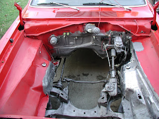
I spent quite a few hours over the weekend removing unnecessary items from the engine bay. I then hit it with degreaser and pressure washed it. I began media blasting the areas that still need to be painted but I ran into trouble. It's been very humid and I kept getting too much moisture in my air lines, so the blast media kept clogging. I had to stop numerous times and clean the lines so the media would flow. I finally had to give up until I get an air line dryer that works better than the one I have been using.

As it turns out, I don't need to be in such a big hurry to paint the engine bay until I decide where the battery and equipment racks will go, and how they will be attached. Welding, and possibly even some sheet metal cutting, will be involved so I'd probably just mess up my paint job anyway. Upon measuring for the racks, I realized that it is going to be a huge challenge finding room for all 14 batteries - well, actually 15 counting the accessory battery. I don't really even know exactly how much room I will have until I get the motor in the car.

Therefore, the next logical step is to work on the necessary parts to adapt the motor to the transmission and get that assembly mounted into the car. I expect this to be one of the most difficult jobs of the entire project so I might as well tackle it now.

Saturday, September 6, 2008

The Old & The New

After a 9 week wait, my electric motor finally arrived yesterday. Today I took a big step and removed the internal combustion engine. I took lots of time to bag and tag all of the parts that will go with the engine to another project. I also weighed everything that will not go back on the Duster so I can keep track of the total weight of the car.

Next, I have to spend some time prepping the engine bay. As with the trunk, I need to complete my paint job. I'll also be building racks to hold the other 14 traction batteries and the motor control equipment. I also need to fabricate mounts for the electric motor.

Tuesday, September 2, 2008

Test Drive

Since the engine is still in the car, I couldn't resist taking a little test drive to see/feel how the weight affected the car. Of course there isn't a gas tank in the car anymore, so I rigged up a gallon jug under the hood. There is also no exhaust system, just open headers. Actually, it didn't seem all that loud so I went ahead and took it for a spin around the neighborhood.

I was quite sensitive to the car sitting lower and could definitely feel the extra weight but it seemed okay to me. I did a couple of test stops to see how the brakes handled it. No problem there although I only went up to about 30 mph. The battery rack didn't fall out so that was a plus.

I did hear a slight noise from the rear end when I coasted. I thought "oh no, the rear end can't handle it". But when I got back home I found that the right rear tire was just barely rubbing toward the front of the car. Those tires were the tallest I could fit under there, so I am not too surprised. It should be an easy fix by bending the wheel well lip in a little.

Load 'Em Up


Finally the time came to load the batteries onto the finished trunk rack. I measured the height of the rear of the car to see how it would handle the 800 or so pounds of extra weight (including the rack). The center of the rear bumper came down just over 4 inches!!! By the way, the first two rows of batteries are just below floor level to leave room for a future supplemental charging generator. The last two rows are staggered higher into the trunk so they will be less noticeable from outside the car.


Actually, I like the way the car sits down over the rear tires. To me, it looks a lot better with this stance. I'm sure glad the previous owner installed those heavy duty leaf springs.

Building The Rear Battery Rack (Part 2)


Building the battery rack without a plan was a slow process. I was very careful to think out each piece, measure everything several times, and grind all of the joints to prep the steel for welding. When all was said and done, it came out exactly as I had first pictured it. When I was finished I sprayed the whole thing with rubberized undercoating as I had done inside the trunk.

By the time I was finished, I had gotten a lot of practice at mig welding and was getting pretty good. I can verify two things that I really already knew but had never experienced. Mig welding WILL sunburn exposed skin. Also, when welding while sitting on the ground, do not let hot sparks bounce up your pant leg.

Building The Rear Battery Rack (Part 1)


I didn't really have an exact plan, just a mental picture of what I wanted to end up with. I had purchased 40 feet of angle iron from a local steel company and just started measuring, cutting and welding.

A Slight Detour


As I mentioned in an earlier post, I wanted to finish out the trunk and I figured this would be a good opportunity to do that. I removed the trunk lid, all of the old weather stripping and spent a day or so prepping for paint.


The underside of the trunk lid came out nice. Inside the trunk I sprayed rubberized undercoating over everything, then sprayed it all red except for the trunk floor. The undercoating will help with the corrosion due to having 12 batteries in the trunk.