Wednesday, October 29, 2008

Lugs: Crimping vs. Soldering

This in not a how-to, it's a how-I-do. If you are planning to do an EV, you should decide which method is right for you. Since this subject has been discussed quite a bit in EV forums, I am going to show how I decided to do my 2/0 cable lugs. I was planning to solder them. There is a great tutorial for that method located here.


But there are some who caution against soldering larger lugs such as this page from the book 'Convert it' by Michael Brown. I have read that crimping is best on welding cable like I am using because it has so many fine strands. In the end, I decided that the best chance I had for consistently good terminations was to crimp.


I started by investing in a good pair of cable shears and a neat little insulation stripping tool.


This gives a good, clean stripped cable without harming even one strand of copper.


I then fill the lug about half full of Noalox, an anti-corrosion compound.


Before slipping the lug on, I slide a small length of shrink tube onto the cable


Then I crimp.

I weigh 175 pounds so I have to strain muscles I don't even have to accomplish this task.


By trial an error I found that supporting the crimping tool on the lip of a bucket while pulling the other handle down with all of my weight works the best. When the bucket or the handle slips, I bruise places that weren't meant to be bruised.


Here is a successfully crimped cable.


Lastly, I use a heat gun to shrink the tube around the lug and cable.

Monday, October 27, 2008

Wiring

I'm making progress on the control wiring - just taking my time to get it right the first time. I got my first taste of making 2/0 cables today. I thought that with the large crimping tool I bought, it would be a little easier. But no, it's a workout crimping those lugs on the cable. I only have about 50 more to do. I think I'll work on the low voltage stuff for a while.

................................................................Oh, now you tell me.

Sunday, October 26, 2008

Control Equipment Layout

The battery restraints have now all been completed, coated, and installed. Today I began to lay out all of the control equipment and system wiring. Almost everything is being installed and pre-wired on a removable plywood panel. This will allow for an organized and contained wiring area. I also placed the battery charger in the trunk where it will likely be mounted.

Saturday, October 25, 2008

Rear Battery Restraints

I've made a little progress since my last post. I have now fabricated the battery restraint system for the trunk batteries and media blasted them.


Today I have to drill a few strategic holes to install them, then coat them with paint or undercoating. I now have a diagram as to how I want to wire the 26 traction batteries. This will necessitate turning a few of the batteries around 180°. After I do that, I can install both the front and rear restraints. Then, it's on to wiring up the controls.

Monday, October 20, 2008

She Carries Her Extra Weight Well

I took a break from working on the car this morning to shoot some photos for a magazine article that will be coming out soon in New Zealand. While I was at it, I took a shot similar to one I had from before I started this conversion.
The top photo is with the old 360 engine in it. The bottom photo is after the conversion and is approximately 900 pounds heavier than with the 360 engine. As I said in another post, I prefer the way it sits now.

Saturday, October 18, 2008

No-Fly Zone


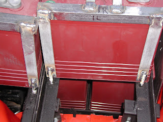
After a couple fun days of cutting, welding and drilling I have finished the underhood battery restraints. These guys won't be flying anywhere now. Before I bolt the brackets down to the angle iron battery racks, I'm going to clean them up with the die grinder, media blast and paint them.


Friday, October 17, 2008

Tachometer

Here is how (for next to nothing) you can supply a proper square wave pulse to a tachometer that will then read the RPM of your electric motor.

It's still a bit chilly outside this morning so I thought I would play with this issue until it warms up enough to go out and work on the car. I have a digital tach in my existing dash and I have intended from the start of this project to use it for the electric motor. It is advantageous to know the RPM of the motor because there is a certain range (around 4000 for mine) that it is most efficient. Knowing what the RPM is at any given speed will allow me to be in the most appropriate gear to get the best performance from my motor and longest life out of my batteries.

These common motors and controllers like I am using have no output for a tach. For months I have been researching on-line about how to make a tach work. I have read about some ingenious and complicated ways that other people have done it - most of which I didn't really understand or was not capable of doing. I have not found one straight forward description that was easy, inexpensive, and sure to work for my setup. So, here is what I did. This should work for any remotely similar setup using a stock automotive tachometer. Maybe this information will fill a void and help someone else.

I had an old 70's type distributor with electronic ignition which I disassembled.

I salvaged what amounts to a 'magnetic gear tooth sensor'. The collar with the ridges on it rotates with the distributor. Every time a ridge passes the sensor magnet, a small pulse of electricity is generated.

I just happen to have a spare digital tach that I have never used. This is good for a test instrument so I hooked it up to a converter and powered it up with 12 volts.


The green wire on this, and most tachs that I have seen, is the sensor input. I tried various ways to get the tach sensor to recognize the little electrical pulses produced by the sensor but it wouldn't. So I went back out to my giant stash-o-parts and found an old 70s ECU (Electronic Control Unit). This is what the gear-tooth sensor originally plugged into.

I plugged the distributor into the mating plug. I then hooked the 12 volt power (positive) to the wire that originally went to the plus side of the coil. Then I hooked the ground (12v negative) to the metal case of the ECU. Lastly, I connected the wire that originally went to the negative side of the coil to the tachometer sensor input (green) wire. As I passed the metal collar past the magnet, the tach registered pulses.

Just to be sure, I affixed the collar to a cordless drill and rotated it at various speeds next to the magnet. The tach registered various RPMs. I did not take a picture of that because I only have two hands:) You'll just have to take my word for it.

So that's where I am today on solving this problem. The next step will be to modify it a bit to make it work for this application. The metal collar will be mounted to the tail shaft of my motor (the small shaft at the front) and will spin with the shaft.

The collar has 8 ridges on it. This means that the sensor generates 8 pulses for every revolution of the old distributor. A distributor rotates once for every two crankshaft rotations in a 4 stroke engine. So by my advanced math calculations, I figure 4 pulses of the sensor will equal one electric motor shaft revolution. Solution: grind down every other ridge so only four pass the magnetic sensor per revolution.

The last piece of the puzzle will be to mount the magnetic portion of the sensor to a stable surface where it can be adjusted close enough to the gear to sense the passing ridges.

Beautiful in it's simplicity! Best of all, it didn't cost me anything. However, these should be common, inexpensive junkyard parts if needed to be purchased.

I'll post the 'final chapter' to this when I finish the installation in the car sometime soon.

Thursday, October 16, 2008

Just A Small Step Backwards


I took care of raising the front battery rack 3/4 inch. Now I have plenty of clearance for the bottom battery terminals. I also cut out a couple of cell access areas on the second rail. If I haven't mentioned it before, all bare steel on the battery racks is coated with a spray-on rubberized undercoating. All of the batteries can go back in tomorrow so I can fabricate the hold-downs for them. We wouldn't want all of those batteries to go flying now would we?

Monday, October 13, 2008

Front Batteries Installed

Fourteen batteries do indeed fit under the hood, with room left over for the motor controller and other equipment.


I still want to make a couple of modifications to the racks. Now that the hood is back on the car, I can see exactly how much clearance the front row of batteries has. I have decided to raise the front battery rack about a half inch to provide a little more space above the terminals on the bottom row. I am also going to cut the angle iron to provide access to the battery cell covers on the bottom batteries, as the water needs to be checked periodically. I will be able to slide the top batteries over enough to gain access to the bottom row for this task.


The car sits very nicely with all of the batteries installed. You can see in the pictures how it compares to the stock '70 Duster (without an engine) next to it. Before I started this project I measured the height of the car at the top of each wheel well centered on the wheel hub. With the weight of the batteries, the car sits about 2 1/2 lower in the rear and only 1 inch lower in the front. I had always disliked how high it was in the rear. Now I think it sits perfectly.

Saturday, October 11, 2008

Do NOT Mess With a Man and His Sawzall


Ok, I was pissed. So I got my sawzall, got into the engine bay and attacked the K-member. Half way through the job, some guy came walking up the driveway behind me. I didn't see him until he got right next to me and he startled me. I popped up with the sawzall still running, sweat pouring off of my face, and a crazed look in my eye. The guy took two steps back as he announced that he was running for County Sheriff and would like to give me a pamphlet. All I can say is, I'm glad he wasn't selling something or he would be missing an arm right now.


Some days you work very hard and make no progress. Some days you work very hard and accomplish a lot but show no progress. Today was that kind of day. Right now, I am back to where I thought I was this morning. The batteries will now fit. It's going to be close at the front of the hood, but the sawzall and I have become good friends.

Damn It!


I'm going to have to go a tad lower on the bottom battery rack. I knew it was going to be close - oh so close. I was a little too conservative on cutting the K-member. Look out now ya bastard. It's time to put away the girly cutoff wheel and bring out the manly sawzall!

IT'S ALIVE!

Today (Friday) was the big day to test the motor. I was a little nervous, mainly thinking about what-ifs. Like what if, for some reason, it didn't work after all off my toil and trouble? Using a 12 volt battery, as per instructions, I hooked it up and away she went. Sweet! I had the rear of the car jacked up so I hooked it up while in gear. The wheels turned! Everything sounded nice and smooth.

After unhooking everything, I went back into the house and discovered a message had been left on my phone. The last piece of the puzzle - my battery charger - has been shipped! Excellent timing! Now I can begin the 'home stretch'.

Engine Bay Prep


All of the battery racks are finally complete. After a good coat of rubberized undercoating, they are ready to install.

I have used the last of my rattle-can red to paint the remainder of the engine bay. Then, while I still had good access to the engine bay, I decided to fashion a plate to block air from coming through the grill. This is a measure to improve the aerodynamic profile of the car.

I just happened to have some thin aluminum sheet that was removed from another car project. Working outside on a nice day using a few simple tools, I made a pretty nice little block-off plate.

What Did I learn Today?

I was using my miter saw to cut metal for the battery racks. After cutting a couple of pieces, I walked over to the bench grinder to smooth out the edges on the cut pieces. When I turned back around, flames were shooting up the wall. Luckily I had a fire extinguisher nearby.


As everything can be a learning opportunity, here is what I learned from this experience.

  • Sparks from cutting metal can actually ignite a fire. I have always wondered.
  • Even though you've never used it, always keep a fire extinguisher handy.
  • When the guy at Home Depot tells you that the saw you are purchasing is not made for cutting metal, there may be a valid reason.
  • If ignoring advice and using a cheap miter saw to cut metal, remove the synthetic sawdust-catching sock on the back of the saw. It is flammable.

Wednesday, October 8, 2008

Racks and Brackets

For clarity, I thought I'd post some pictures of what I have ended up with for my removable racks. The rack assembles will bolt to the brackets I have welded to the frame rail. Now I can finish welding everything, media blast, paint, and install it all.

Last Battery Rack Problem Solved

I gave up trying to get a brace down to the frame next to the steering box on the 'problem' battery rack. I decided to just weld a bracket to the side of the engine bay, thinking it would be strong enough. Wrong! After I welded it on I had second thoughts and then discovered the 'right' way to do it.

I hate to admit it here, but the solution was pretty simple. I really should have thought of it before I had to cut through all of my welds. But, for some reason I just didn't. Anyway, after I got the bracket off and ground everything smooth again (with my new die grinder), I just drilled two holes and put bolts through the bracket, the engine bay, and through the shock mount on the outside of the engine bay. This will be plenty strong enough.

Ever Have One of Those Days?

I finally had a day off from my real job today, so I planned to work all day on the battery racks. The first thing I did was tighten down the one in the picture so I could work on the other end of it. When I tightened the nuts, I noticed that I had tacked the frame bracket on crooked. Ok, minor setback.

I removed the rack and cut my tack welds off the bracket. When I went to grind the welds down, my die grinder broke. Ok, another setback. So I went to Home Depot and purchased a new die grinder.

On the way home I stopped to get a Dr Pepper. When I came back outside the store, I noticed coolant leaking out from under my truck. I hurried home before it started to overheat. From what I could see, the coolant was coming from the water pump. Ok, another setback.

I didn't want to waste my whole day off working on my truck, so I took it to a local shop and had them give me a ride back home. By that time, the day was half gone and I had accomplished nothing but spending money I didn't plan on. The thought crossed my mind to NOT work on the Duster for fear of something else going wrong. But after a lunch break, I regrouped and figured the odds were in my favor for the rest of the day. I actually did get some work done without anything else going haywire.

I am posting this to remind myself later that I experienced a lot of unrelated obstacles to accomplishing this conversion.

Sunday, October 5, 2008

Problem Solving......Mopar Purists, Better Just Look Away

As we all know, most problems have several possible solutions. We have to choose the best solution according to our needs. I have not mentioned this problem in the blog thus far because I wanted to wait until I knew for sure what I was going to do about it. Well, today is the day :)

This problem begins with my choice of voltage. The 'usual' and most common voltage used for heavier vehicles is 144 volts. I wanted to ensure that my performance would be at least as good as other 4,000 pound conversions so I chose to use 156 volts and found a reasonably priced and readily available motor controller that could handle that voltage. This necessitated using 26 batteries instead of 24.

I have been solidly committed to using 26 batteries from the start and that has never been negotiable. However, placement of those two 'extra' batteries has been something in the back of my mind. For proper weight distribution, I wanted, if at all possible, to place 12 batteries in the rear and 14 under the hood. I knew 14 under the hood would be tight. The best solution was to place 4 batteries down low in front of the motor, with the remaining batteries on the racks above the motor. The problem with this configuration is the limited height I have available.

So ok, I'm getting closer to coming to the point here :) My number one rule for this project is not to 'harm' this classic Mopar. Cutting some sheet metal is ok. Welding to the frame is ok. But THIS is something I really did not want to have to do. However, going back to my first paragraph, this was the best solution to achieve the end result I want. So, without further ado...


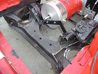
Cutting and modifying the K-frame allowed me to position the bottom rack low enough to get the clearance I need. In fact, if my measurements are correct I don't even have a half inch to spare. Had it been a rack for just two batteries, I would not have had a problem. Oh well, I guess it's not the end of the world, but it was still traumatic for me to perform that surgery.

Saturday, October 4, 2008

Slow progress on the battery racks

I'm mildly frustrated that this part of the job is taking me so long to complete. Like the rear battery racks, I didn't have much of a a set plan when I began work on them, just an idea of what I wanted to end up with. The rear racks went together quickly with no problems. However, The under-hood racks are proving to be much more difficult. Problem number one, as I mentioned in another post, is that I need these batteries as close to the underside of the hood as possible. Well, the hood slopes, so each cross bar is at a slightly different level, as illustrated in this picture.


Secondly, except for on the front two bars, each brace needs to attach to the frame in a different manner. Therefore, each one is its own special little custom job. I've almost got it all ready to make permanent except for the brace above the steering box.

There is very little room to drop an angle iron brace to the frame rail. So, the next job will be to get serious and figure out how I want to accomplish this task so I can finally be done with these and move on to the home stretch.

Replaced the Brace

I like this brace much better than the first one I made. It was well worth the extra time.

Thursday, October 2, 2008

Measure, Cut, Fit, Grind, Weld, Drill, Repeat

These battery racks are proving to be quite a challenge. Most of the difficulty I'm having is designing them strong enough while keeping them removable. It has also been time consuming to make sure all of the batteries will end up just below the bottom of the hood - without the benefit of having the hood on to measure against. But, I'm determined to do a good job on these no matter how long it takes me. Today I spent way too long fabricating this mount...


...only to later decide that it won't be strong enough for me. It will easily hold the dead weight but I am afraid that it won't stand up well enough to any lateral forces. On the next rack I came up with what I think is a much better design. So I'm going to go back and redo the first one. There is a lot of measuring, cutting, grinding, welding and drilling with these little suckers. Man, I'm glad I don't do this for a living. Here is a picture of the rack support design I'm going with (not welded in yet). I still have a few more to make.